One of the best sailing days this year so far reminded me of something that I personally need to be reminded of quite frequently. Maybe the insight is of some value to you too. It deals with a few tensions, one of which is mentioned in the title and another that is related. These tensions happened to become apparent in today’s sailing trip, but seem to me to be quite general in our daily lives, whether related to work, sports or whatever. They are:
- Pressure vs. progress
- Feeling vs. fact
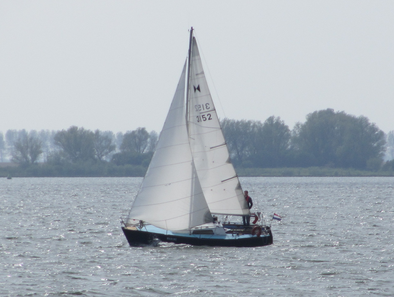
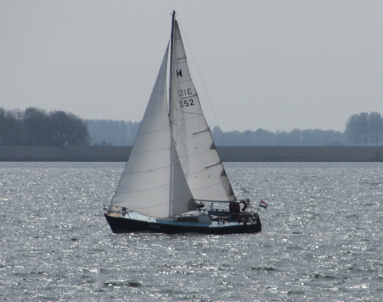
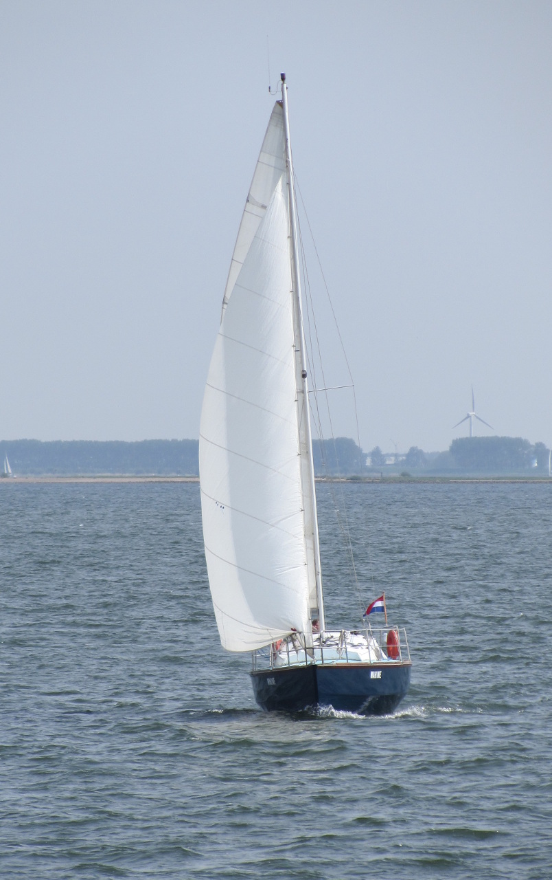
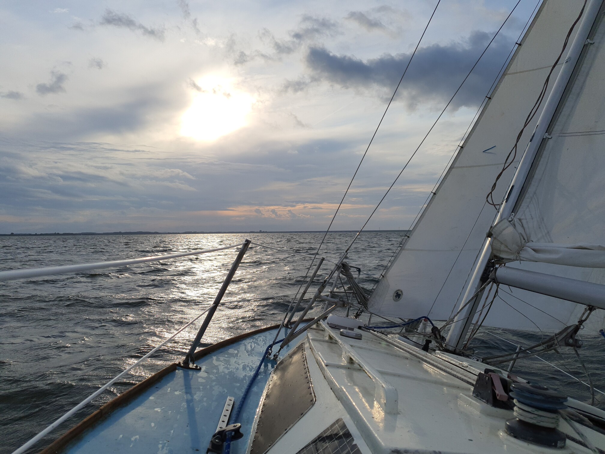
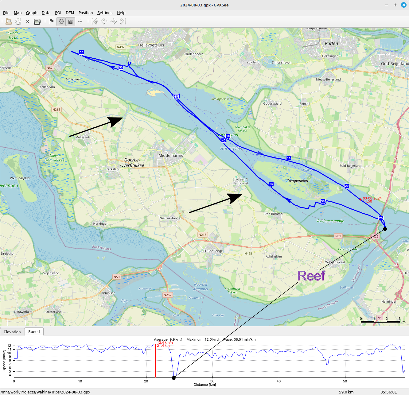
So what made this such a lovely day to sail? A nice strong breeze from the west/south-west allowing for a fast downwind run to the bridge and going back upwind with a minimal amount of tacking. See the route in the image:
There were some squalls with pretty strong winds so on the way back I decided to put a reef in (reduce the main sail area) and then answer the question: do I leave the big genoa on or do I replace it with a small headsail? I decided on the latter, which turned out to be a good idea.
After passing under the bridge again, I initially regretted my the decision. The squall had passed and the wind dropped significantly. I felt underpowered, so I had a look at the GPS: 5kn (~9km/h). That is actually not bad going upwind close hauled! I know the boat would not have done better with the genoa up, maybe even a bit worse. So what was going on? Why was my feeling wrong?
I started sailing as a young kid and spent many summers sailing on a Laser (small one person dinghy). There are different rigs for this type of boat and I had the big one intended for 80+kg. I don’t know my weight at the time and it obviously increased with the years, but it must have been below 60kg for most of those years. Long story short, for most wind conditions I had way to much sail up and was completely used to feeling lots of wind pressure, but did I make good speed? Downwind yes, but otherwise, probably not so much. I learned later that I also didn’t trim the boat quite right, but still. The lesson to be learned: it’s not about feeling pressure, it’s about moving forward.
Later as a student, I rowed competitively and had a similar experience. The boat would be fastest not when feeling lots of pressure, but when feeling smooth. Just like with the big sail, feeling lots of pressure when pulling the oar meant I was working very hard and thus I felt I should be moving quickly, but that wasn’t necessarily the case. It’s not just about the amount of power you put in, but also about how effective that power is converted to speed into the direction you want to go in.
Moral of the story: progress is more important than pressure and your feelings may deceive you, so check and measure to tune your feeling for the best action towards achieving your goals whatever they may be.