
A few weeks ago, the motor of my laundry dryer started stuttering, sometimes making a humming noise, sometimes stopping all together. I’ve only had this/a dryer for a couple of years –it was my mother’s before–, so I thought: all right, I’ll just hang the laundry on a rack like I used to and save the environment while at it!
However, not having talent for/interest in house keeping related stuff, I’d become rather appreciative of the convenience. And annoyingly, the dryer wouldn’t fail completely, but occasionally came back to life, giving me the impression that it ought to be fixable. I was definitely not going to buy a new one.
So I hopped on to the Google and Youtube click wagon: “dryer motor humming not running”. Analysis: bad motor capacitor or motor short. All right then, lets get to it!
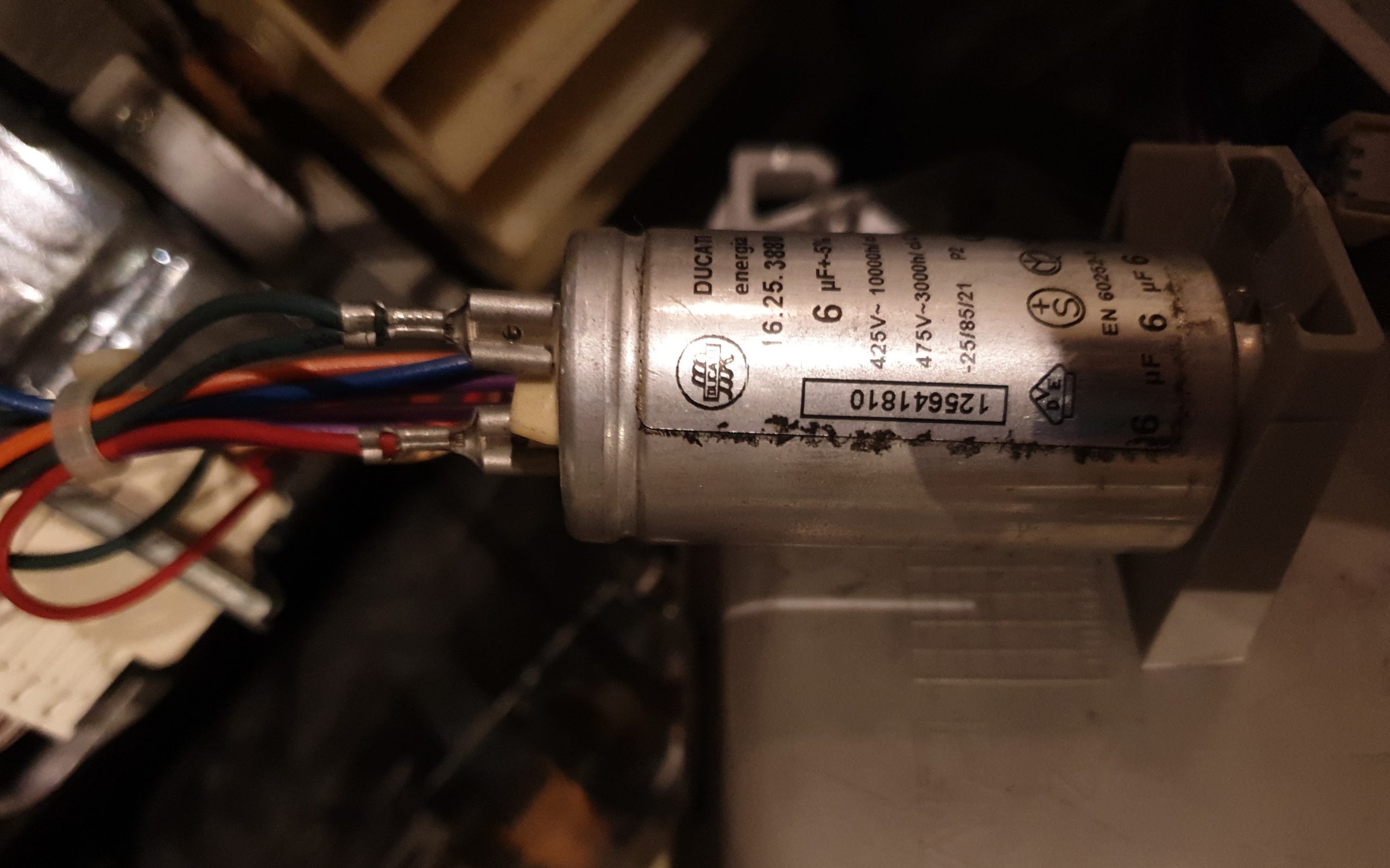
First, the motor capacitor. It’s there because the type of motor used –an asynchronous motor– actually requires a three-phase ‘rotating’ current to spin, while we only get a single phase –alternating– current from the power grid. A third phase is faked by shifting the phase of the alternating current, which you can do with a capacitor. I measured the capacitance at 5.5muF. As you can see it says 6muF +/-5%, so it was out of spec, but I didn’t really feel it deviated enough to cause any problems, but oh well, let’s replace it just in case! Next:
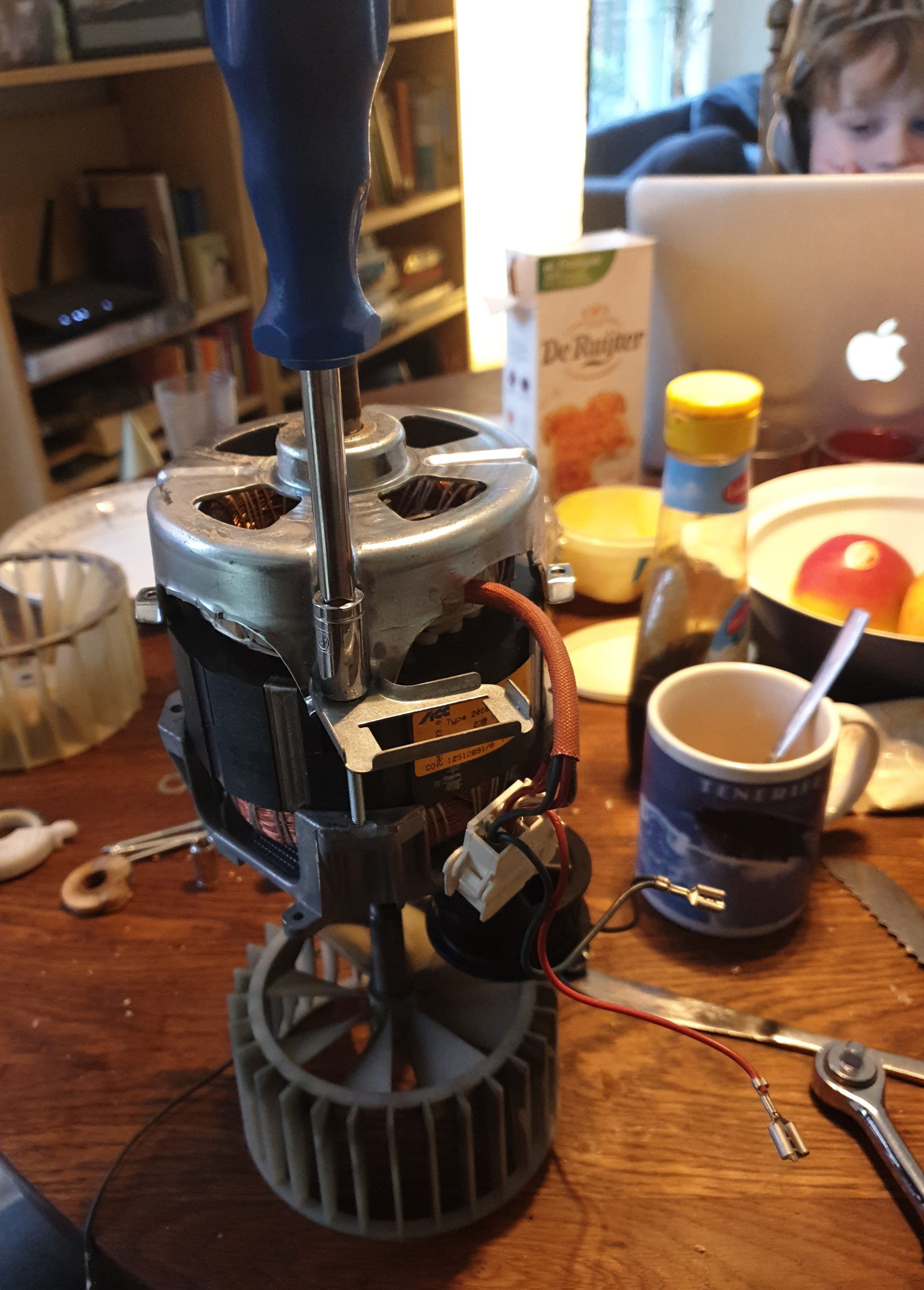
Taking apart the motor and checking it for possible locations of a short –the kid in the background is my son doing his home schooling work :)–. Nothing to see. I sprayed some varnish into it in case some of the wiring insulation was damaged and put it back together.
Proof of the pudding: I turned the dryer on. Yes it worked! … but not for long. The motor stopped again. Same issue still.
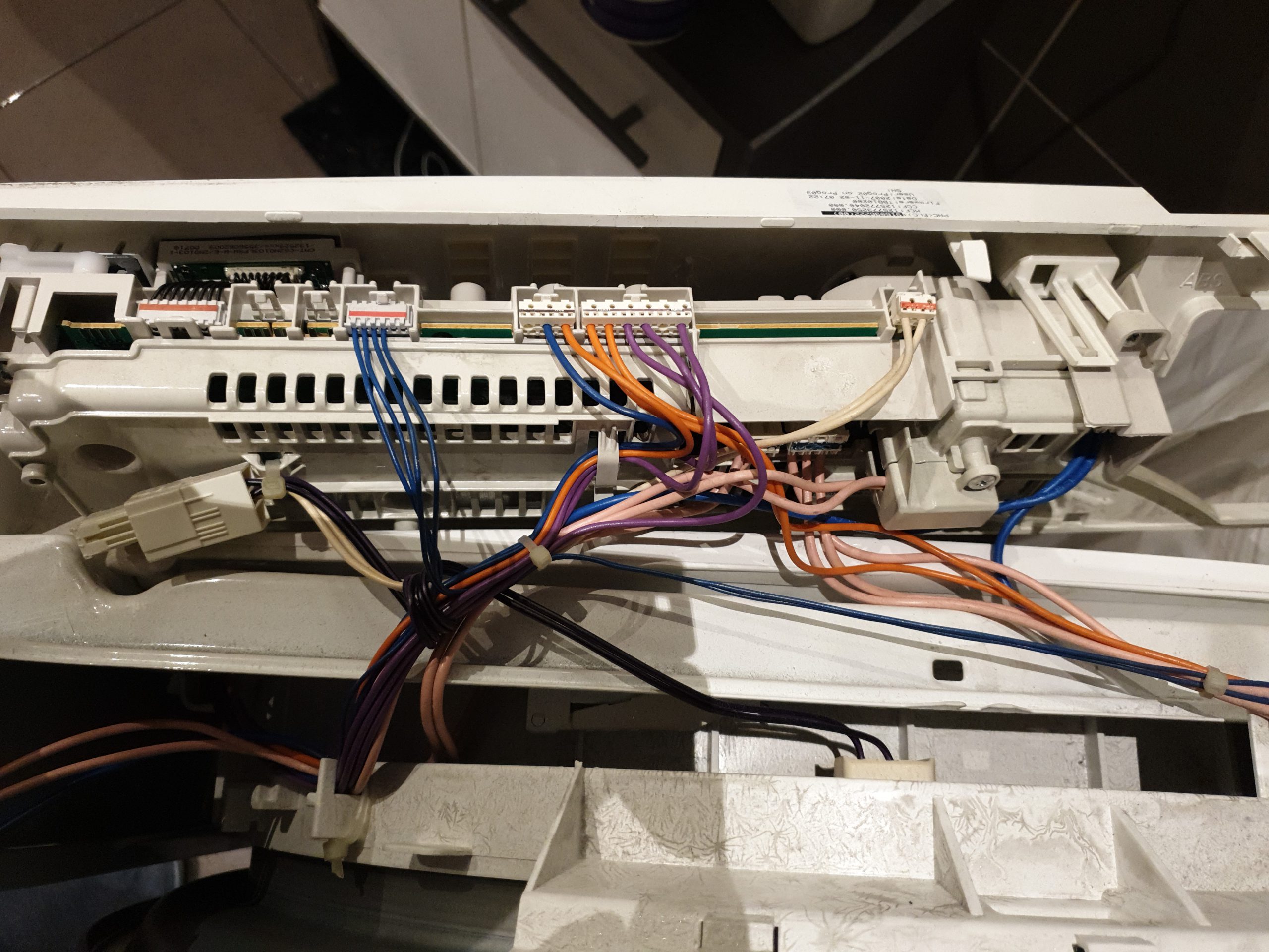
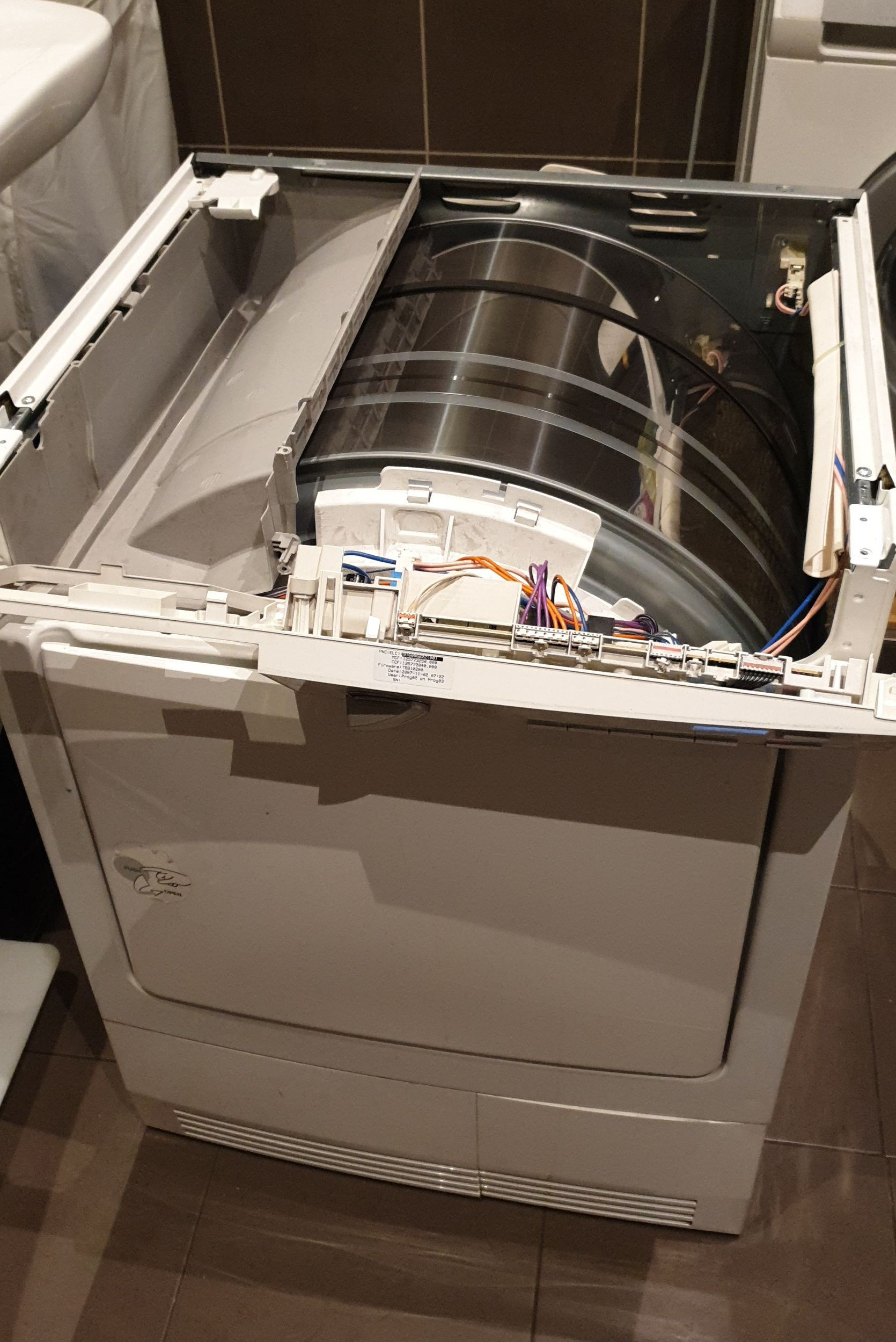
OK then. What else could it be? Was the motor getting any juice at all when it didn’t run? I should of course have checked/measured that immediately. No, it wasn’t getting any, so next to check was the controller board that drives everything. I guess I hadn’t checked this before, because I was afraid the controller board could be the issue and feared my chances of being able to fix it would be greatly reduced if that turned out to be the culprit. Anyway, there was no escaping it now. Let’s get it out!
The board inside looks like this. It’s apparently a very common controller board, made by Electrolux, and is used in many types and makes of tumble dryer (image of the internet):
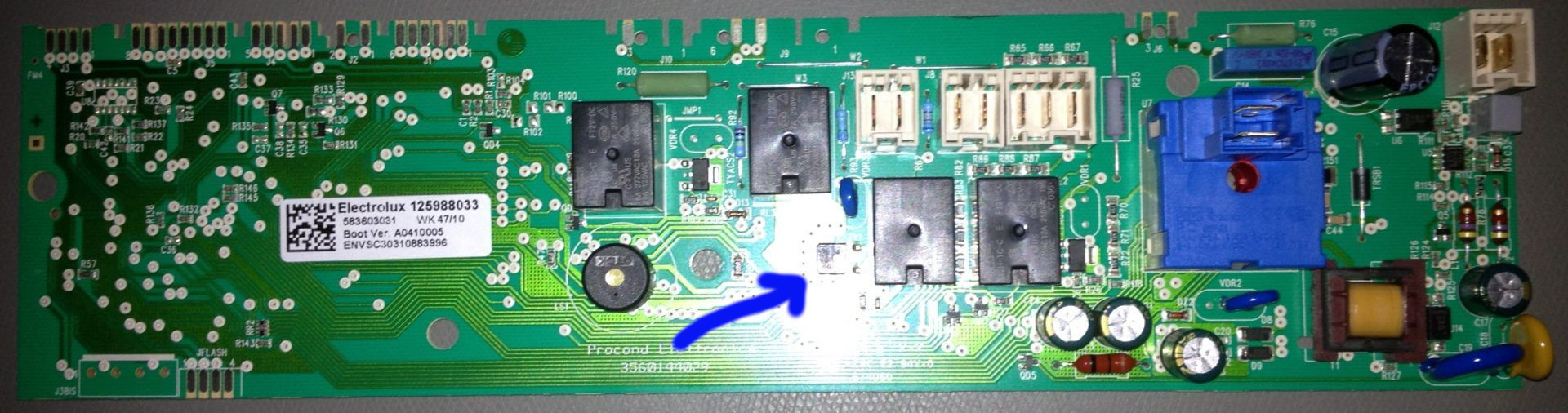
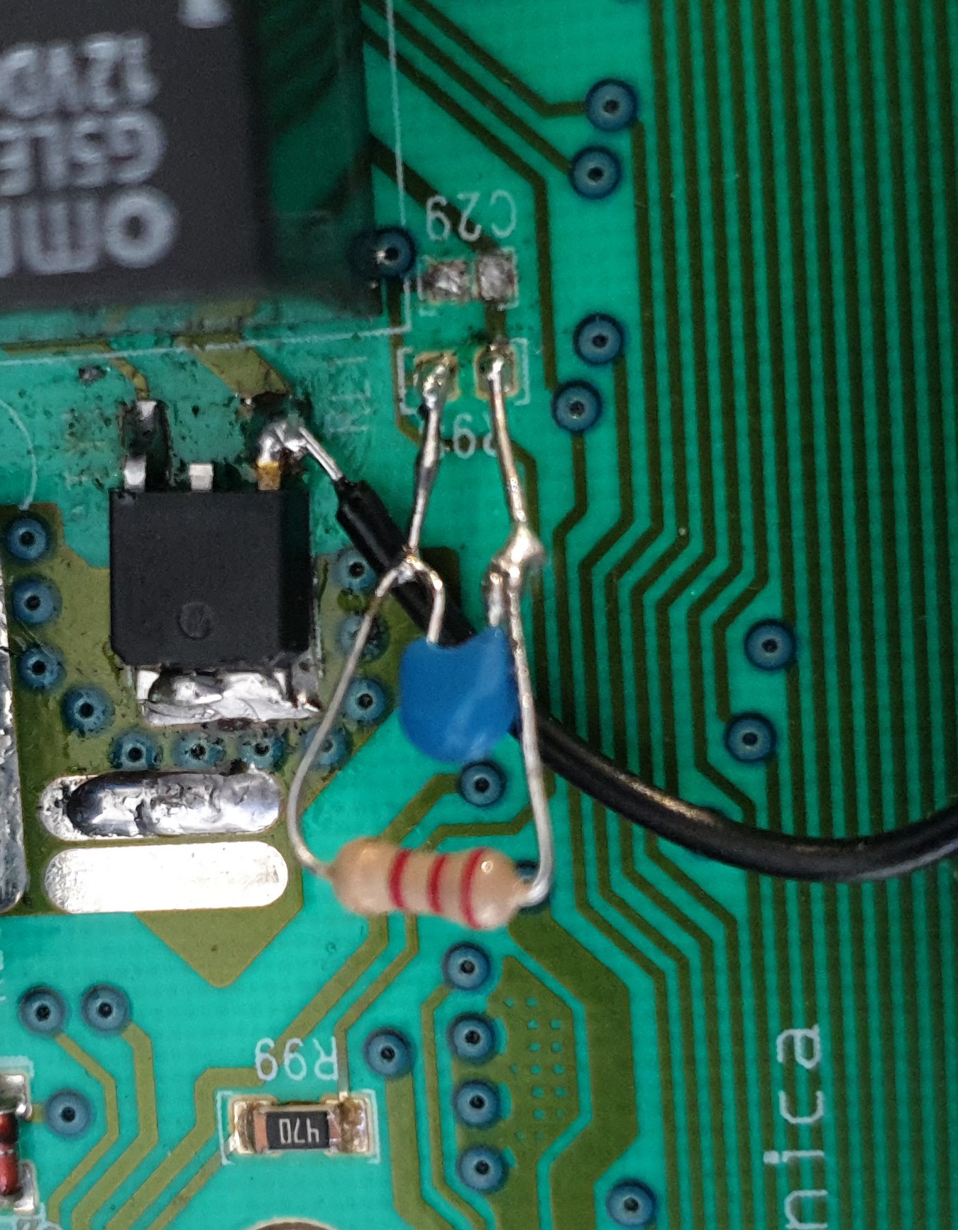
Nothing on my board looked burned or damaged. I traced a lot of paths and found out that the little black thing at the arrow is a “triac“, a sort of electronic switch that switches the motor on and off. A new candidate for replacement. I ordered one, waited a few days for it to arrive, soldered it on and….
Yes! the machine was working! …. but not for long. Same issue. The motor would stop after a while. Bummer. Quod nunc?
I decided the only way forward was to do live testing. Yes, live testing a 220V powered device is dangerous. Don’t try this at home kids!
Anyway, when measuring voltages on the triac while switched on, the motor would usually switch on only due to me measuring the voltages on the triac. WTF? I must be getting warmer! So if the triac itself isn’t the issue than it must be something close driving the triac… I noticed that the voltage driving the triac, the voltage between the gate and the input terminal, was 0.48V when the motor was running, but only 0.28V when it wasn’t running, but should have been. Otherwise it was just 0V. First, I attempted to better understand the circuit. It’s not complete, but it looks roughly like this:
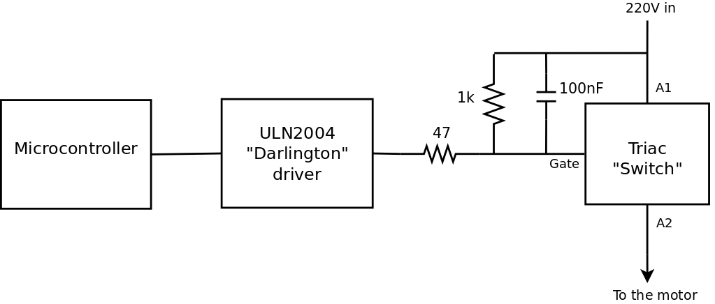
It seemed unlikely to me that the microcontroller would be broken or somehow ‘confused’. The “darlington” driver, that is used to convert the logic output of the microcontroller to an actual current is a 7 driver array chip with 16 pins. It costs only 30 cents, but I didn’t feel like trying to replace it! The 47 ohm resistor checked out fine when measured… Now the 1k resistor and 100nF capacitor… I couldn’t measure them, because the triac also has an internal resistance between the gate and A1. They look like they’re just there to protect the triac or the driver from peak voltages or something and if anything, they drag the voltage between gate and A1 down, so I thought, h*ll, let’s take them off and test…
HALLELUJAH!!!! The machine was working like a charm! I did feel a little worried about removing the components so I put back a 2k resistor and a 100nF capacitor. The machine still ran fine!
Very long story short: the dryer is working again and I am annoyingly pleased with myself for having fixed it!!
I am still not entirely sure whether the removed components were damaged or whether the driver chip is failing and changing the resistor value is just enough to make it go, but who cares as long as it runs. Considering the time I spent on it, it’s obviously not economically viable to do a thing like this. A new dryer would have been cheaper, but I learned a lot from this exercise, about single phase asynchronous motors, triacs, darlington drivers and about the whole operation of a condensor tumble dryer like this. Also, I didn’t waste an otherwise perfectly good dryer. At least not for the moment. That feels kind of cool.